Table of Contents
A shunt resistor translates current into a measurable voltage, but it also inserts loss and heat into the power path. The usable value must create enough signal for the amplifier without exceeding voltage-drop, power, temperature, or fault-energy limits.
The shunt and its PCB connection form one component. A precision data-sheet tolerance cannot correct milliohms of copper and solder included by poor sense routing.
How do you choose shunt resistance from signal and power limits?
Choose a shunt resistance that produces enough measurable voltage at the required current while remaining below the circuit’s allowed voltage drop and dissipation. Use VSHUNT = I × R and P = I²R, including amplifier offset, noise, gain error, ADC range, and resolution when defining the minimum useful signal.
Use resistance tolerance at the measurement reference temperature and account for calibration. If firmware calibrates gain at production, define what remains: temperature drift, aging, board stress, and nonlinear self-heating.
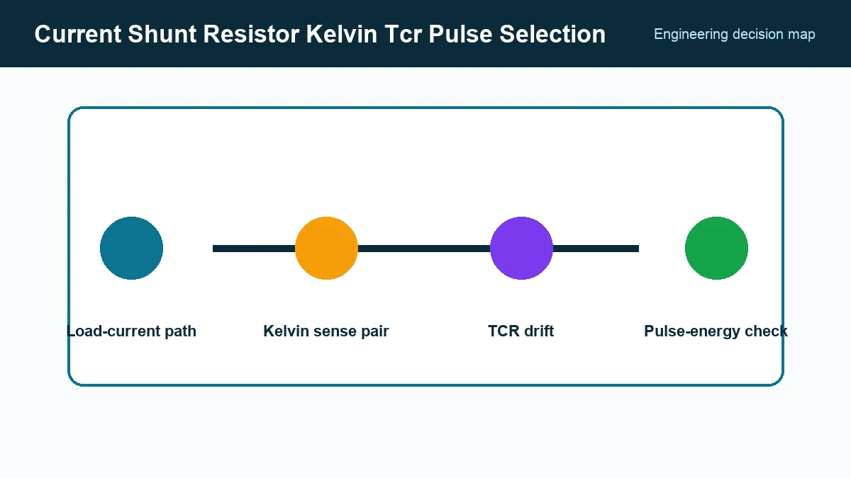
How do TCR and self-heating change a current shunt’s resistance?
The shunt’s temperature coefficient of resistance (TCR) converts element-temperature change into resistance drift. Estimate element temperature from local ambient, self-heating, and nearby heat sources using thermal data for the actual land pattern and copper, then apply the specified TCR over the relevant range.
ROHM’s current-sensing resistor design guidance, accessed September 24, 2026, discusses resistance value, rated power, TCR, and layout considerations. Treat the published power rating as conditional on terminal temperature, board area, and derating—not as a universal continuous-current limit.
For wide-range measurement, the hottest high-current point and the smallest low-current signal can set opposite requirements. One shunt may not cover both without a programmable-gain amplifier or separate ranges.
Route force current away from sense voltage
For a four-terminal part, connect high current through the force terminals and route a symmetric differential pair from the sense terminals. For a two-terminal part, take the sense traces from the inner edges of the pads at defined equipotential points.
Avoid sharing sense vias with load current. Keep the pair together and away from switching nodes. Copper pours should be geometrically balanced so current does not crowd through one terminal and create a lateral voltage gradient.
Thermoelectric voltages arise where dissimilar metals sit at different temperatures. They matter when measuring microvolt-level shunt signals or bidirectional current near zero. Symmetric layout and thermal conditions reduce this error.
Evaluate pulses with the manufacturer’s curve
A surge can satisfy average-power limits while exceeding short-time element temperature, terminal current, or film current density. Use the exact part’s single-pulse and repetitive-pulse data. Compare pulse energy, peak power, duration, duty cycle, waveform shape, and ambient derating.
Fault current may last until a fuse, eFuse, or controller trips. Combine protection tolerances to find the worst clearing energy. Verify resistance shift after representative pulses; survival without an open circuit does not prove the shunt remains accurate.
For bidirectional motor or converter currents, include RMS heating from ripple. A current waveform with low average can still create substantial I²R loss.
Validate measurement and thermal behavior together
Measure shunt voltage and current with independent equipment across load and temperature. Use a thermal camera or attached sensor with a documented emissivity method, and allow steady state where appropriate. Apply fault pulses to dedicated samples and remeasure resistance.
Release documentation should state resistance, tolerance, TCR range, technology, terminal style, continuous current, permitted drop, PCB footprint and copper, ambient limit, calculated element temperature, pulse profile, calibration approach, and Kelvin routing detail. This gives procurement electrical and construction limits that a lower-price milliohm value cannot bypass.
Frequently Asked Questions (FAQ)
Why use a four-terminal shunt resistor?
Separate force and sense terminals keep most terminal and solder-joint voltage drop out of the measurement. PCB routing must still connect the sense traces at the intended Kelvin points.
Is the shunt's power rating enough for a short current pulse?
No. Use the manufacturer's pulse-overload or energy curve for the pulse width, amplitude, repetition, ambient, and mounting. Average power alone can hide damaging peak temperature or current density.
Does production gain calibration remove shunt temperature drift?
No. Calibration at one current and temperature can correct the measured gain at that condition, but temperature drift, nonlinear self-heating, aging, and board stress remain unless separately characterized and compensated. Keep the calibration point and residual error limits in the qualification record.