Table of Contents
A power inductor quote is difficult to compare when one supplier highlights saturation current and another highlights temperature-rise current. Both numbers can be correct while describing different limits. A replacement selected from the larger headline value can lose too much inductance during a transient or run too hot at continuous load.
For an OEM or EMS buyer, the useful deliverable is an approved operating envelope tied to a complete ordering code. Engineering supplies the waveform and thermal limits; procurement asks each supplier to demonstrate the same requirements. This separates an available alternate from an electrically acceptable alternate.
How should buyers compare Isat and Irms between suppliers?
Compare saturation current, Isat, at the same allowed percentage reduction in inductance, and RMS current, Irms, at the same temperature-rise condition. Then check both against the application’s peak and RMS currents. Neither rating substitutes for the other.
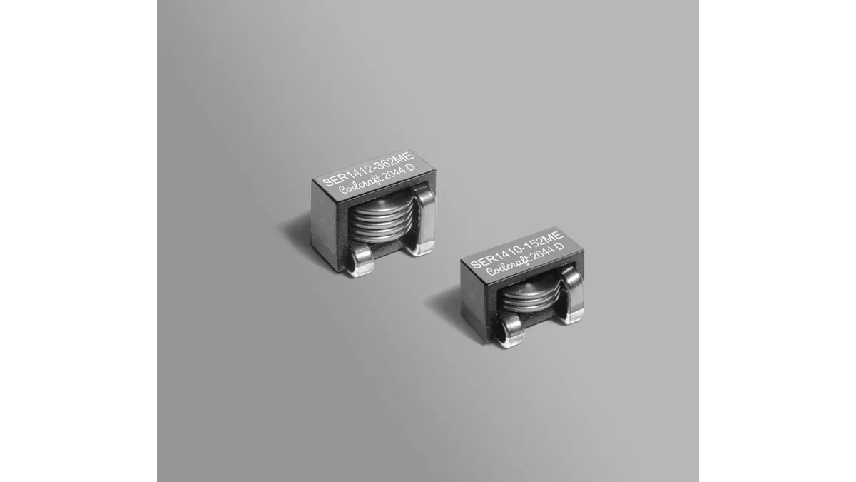
Coilcraft’s inductor-selection discussion explains why different saturation definitions can make catalog comparisons misleading. A useful offer therefore includes the inductance-versus-current curve and the conditions behind its current ratings.
The SER1400 data sheet makes the distinction visible: it lists saturation currents for 10%, 20% and 30% inductance drops, plus separate RMS currents for 20°C and 40°C temperature rises. Those columns are different comparison choices, not interchangeable specifications.
A buyer’s normalization sheet can be short:
| Field | Common comparison basis | Reason to stop approval |
|---|---|---|
| Inductance | Minimum required value at peak current and relevant temperature | Only a zero-bias nominal value is available |
| Saturation | Same percentage-drop criterion | Candidate uses a more permissive drop |
| Heating | Actual RMS current and board conditions | Rating assumes a cooler environment |
| Resistance | Maximum DCR and temperature correction | Quote provides typical room-temperature DCR only |
| Mechanics | Land pattern, height, terminations and assembly process | Package name matches but drawing does not |
Which current should be used for a buck-converter inductor?
For approximately triangular ripple in continuous conduction, use load current plus half the peak-to-peak ripple for the steady-state peak, and combine the DC and ripple contributions for RMS current. Startup, overload and transient peaks must be evaluated separately.
For a hypothetical 8 A load with 3 A peak-to-peak triangular ripple:
- Steady-state peak current = 8 + 3 / 2 = 9.5 A.
- RMS current = √(8² + 3² / 12) = 8.05 A.
These values create two different purchasing checks. The inductance must remain adequate at 9.5 A, while continuous heating must be acceptable around 8.05 A RMS. If the controller can allow a 12 A peak before limiting, the saturation assessment needs that additional condition.
This calculation is a screening model. Discontinuous operation, pulse skipping and changing ripple amplitude require the actual waveform. The surrounding buck-converter operating envelope determines which current cases matter.
Why can a low-DCR alternate still run too hot?
Low DC resistance reduces winding conduction loss, but it does not describe every loss mechanism or the installed heat path. Switching frequency, ripple amplitude, core material, nearby heat sources and airflow can change the temperature reached on the board.
As an illustrative calculation, 8.05 A through 12 mΩ produces about 0.78 W of DC-resistance loss. If hot resistance rises to 16 mΩ, that term becomes about 1.04 W. These figures exclude core and AC winding losses and do not establish final component temperature.
Ask for the conditions behind any loss model. A model at one frequency and ripple level should not be copied into a different converter merely because nominal inductance matches. Also distinguish maximum component temperature from maximum ambient temperature: self-heating consumes part of the available temperature margin.
Release the alternate with its comparison conditions
The approval record should retain the original and candidate ordering codes, data-sheet revisions, current waveforms, minimum inductance requirement, allowable temperature, mechanical drawing comparison and board-test result. Record which limits are guaranteed and which curves are typical characterization.
The purchasing line can then require the approved code, packing form and manufacturer change notification route. A subsequent offer with a different tolerance, termination or series returns to that record for review. Procurement gains a repeatable acceptance basis instead of repeatedly asking whether a catalog current rating is “high enough.”
Frequently Asked Questions (FAQ)
Does a higher Isat rating always mean a larger usable current?
No. The rating may allow a greater percentage loss of inductance. Compare inductance at the required current and temperature, using the same loss criterion.
Should an inductor RFQ include a manufacturer series or a full ordering code?
Use the full ordering code, including inductance, tolerance, termination and packing options. A series contains parts with different current, resistance and mechanical limits.
Can incoming inductance testing replace a converter load test?
No. A small-signal measurement checks only its stated conditions. Converter qualification must also address DC bias, ripple, transient current and temperature.