Table of Contents
An I2C EEPROM replacement may respond at the expected bus address and still damage stored data when firmware writes across a page boundary. A read-only bring-up test will miss that failure mode.
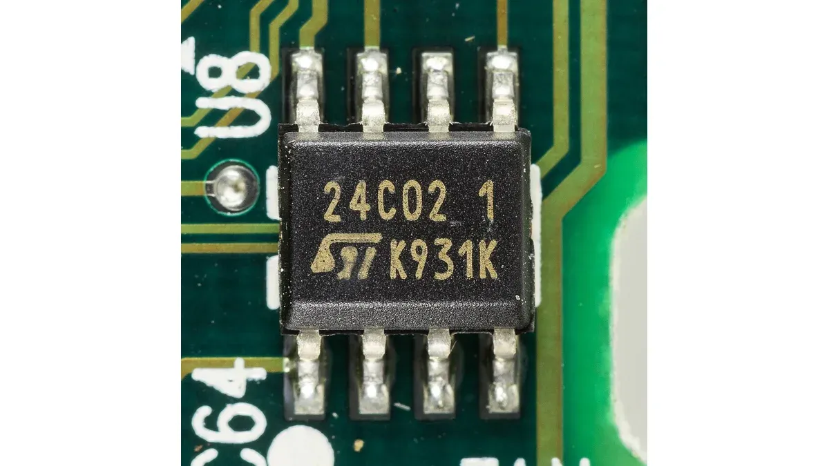
For electrically erasable programmable read-only memory (EEPROM), software compatibility is part of the purchase specification. The comparison must cover the wire protocol and write behavior as well as capacity, package and voltage. The worked example below uses the Microchip 24LC256 protocol; it does not describe every I2C memory.
What must match before an I2C EEPROM is interchangeable?
Match the supply and bus conditions, pin functions, device-address interpretation, memory-address format, page-write behavior and write-protection rules. Equal capacity and an eight-pin package are insufficient evidence of firmware compatibility.
There are two different addresses to record: the I2C device address that selects the chip, and the memory address that selects a byte inside it. Mixing these terms makes supplier comparisons ambiguous. Similarly, a seven-bit device address of 0x50 and a transmitted write control byte of 0xA0 can describe the same bus transaction; the latter includes the read/write bit.
| Interface item | Comparison record | Failure that a basic read may miss |
|---|---|---|
| Address pins | Pin states and how the device uses them | Collision with another bus device |
| Memory address | Byte count and significant bits | Data written to a different location |
| Page size | Physical page boundary and wrap rule | Earlier data overwritten within a page |
| Write protection | Pin function and protected scope | Writes unexpectedly blocked or allowed |
| Timing | Bus limits and write-completion method | Intermittent errors under continuous writes |
Why does a page write corrupt data at a boundary?
On devices with page-wrap behavior, a write that crosses the current physical page boundary returns to the start of that page instead of continuing to the next one. Firmware must split the request into transactions that respect the device’s page size.
The Microchip 24AA256/24LC256/24FC256 data sheet, sections 6 and 7, specifies a 64-byte page buffer and describes both wrapping and acknowledge polling. These are device-specific protocol facts, not assumptions to copy to a different family.
Consider a hypothetical 20-byte write beginning at 0x0038. For a 64-byte page, only eight locations remain before the boundary:
- Transaction one writes eight bytes at 0x0038 through 0x003F.
- After that write completes, transaction two writes twelve bytes at 0x0040 through 0x004B.
A driver can calculate the next chunk as min(bytes remaining, page size − address modulo page size). It must also respect the controller’s transaction-size limit. The splitting rule belongs in the memory driver; increasing an application buffer does not change the EEPROM’s physical page.
How should firmware wait for an EEPROM write to finish?
Use the completion mechanism specified by the device and enforce a bounded timeout. For the cited Microchip family, acknowledge polling distinguishes an internal write cycle that is still busy from one that has completed.
Do not interpret every missing acknowledgment as “busy.” The same bus symptom can result from an absent device, wrong address or electrical fault. A driver needs context: a valid write was just issued, the device is within its allowed completion interval, and a timeout leads to a reported error rather than an infinite retry loop.
If existing firmware uses a fixed delay, compare that delay with the replacement’s maximum write-cycle requirement under the applicable conditions. A typical timing figure is not a safe substitute for that limit. Changing to polling also needs a firmware regression check, including error recovery and interactions with other devices sharing the bus.
Which tests expose an alternate that only passes a read check?
Exercise boundary writes, protection states, repeated updates and power interruption using the actual application driver. The expected data and recovery outcome should be defined before each test.
Start writes immediately before, on and after a page boundary. Use patterns that make wrapped bytes distinguishable from intended data. Test the highest used memory address, verify address-pin combinations present on the board and check recovery after a bounded timeout.
For records spanning multiple writes, validate the application’s integrity scheme separately: a successful individual page write does not make a multi-page update atomic. Preserve the firmware revision and device ordering code in the alternate approval so that a later software change does not silently invalidate the comparison.
If the project is deciding between memory technologies rather than qualifying an EEPROM alternate, the FRAM versus EEPROM guide addresses the different endurance and retention tradeoff.
Frequently Asked Questions (FAQ)
Does a larger EEPROM preserve the same software interface?
Not necessarily. A capacity change can alter address-byte count, control-byte address bits, page size or address-pin behavior. Check the exact device protocol before retaining the existing driver.
Can readback prove that a write will survive power loss?
Readback confirms the data visible at that moment. It does not establish behavior during an interrupted write or the integrity of a multi-page record. Those conditions need separate validation.
Should endurance be compared using only the largest cycle count?
No. Compare the endurance specification with its temperature, voltage, retention and write conditions, then map it to the application write pattern. A headline cycle count alone is insufficient.