Table of Contents
Two Ethernet transformer modules can share a footprint and turns ratio while connecting their center taps differently. With Power over Ethernet (PoE), a replacement must also preserve the cable-side power path and the current capability required by the design.
A purchasing cross-reference should start with the exact physical-layer transceiver, or PHY, and its reference circuit. “Gigabit Ethernet magnetics” is a product category, not a complete interchangeable-part specification.
Which specifications make Ethernet magnetics interchangeable?
Interchangeability requires compatible winding connections, turns ratio, center taps, PHY electrical requirements, isolation ratings, package geometry and any PoE current path. Matching the catalog speed and footprint establishes only part of that comparison.
Microchip’s magnetics guide explains transformer selection in relation to PHY operation and circuit requirements. Its suggested magnetics application note also illustrates why recommendations have a device-specific scope. These documents support the engineering method; they do not establish present-day inventory or blanket approval of every listed part.
Ask the supplier for the complete manufacturer drawing and electrical specification of the exact offered code. A distributor’s short description is insufficient when center-tap or termination variants share a family name.
Map the signal path before comparing prices
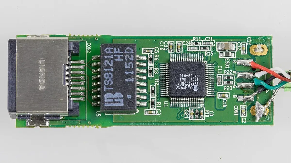
Create a pin-by-pin comparison from PHY to cable. For an integrated magnetic jack, include internal resistors, capacitors, shielding connections and LEDs where present. Mark an internal connection as unknown until the manufacturer drawing resolves it.
| Comparison field | Question for the candidate |
|---|---|
| PHY-side windings | Are channel assignment, polarity and center taps compatible with the PHY circuit? |
| Cable-side windings | Do pair mapping and winding connections match the connector and power architecture? |
| Common-mode elements | Is their placement and implementation compatible with the reference design? |
| Internal termination | Are resistors and capacitors included, omitted or connected differently? |
| Mechanical drawing | Do orientation, keep-outs, pin dimensions and connector position fit? |
This matrix should identify a specific difference and its consequence. A green “same package” cell cannot override a changed internal network.
Why do center taps and PoE ratings need separate checks?
Center taps can serve different electrical purposes on the PHY and cable sides, while PoE adds current and insulation constraints to the cable-side circuit. Connecting a candidate according to the old module’s pin numbers can therefore produce the wrong bias or power path.
Use the PHY manufacturer’s required bias arrangement and the magnetics manufacturer’s current and thermal ratings. Do not assume that every center tap should be tied to the same supply, or that a module without an explicit PoE rating can carry the application’s power current.
Evaluate current imbalance, winding resistance, temperature rise and the specified operating range using the relevant documentation. The required assessment depends on the PoE implementation and the actual module. Controller power classification is addressed separately in the PoE powered-device controller selection guide.
How should electrical performance be compared?
Compare electrical limits under equivalent test conditions and over the frequency and temperature range required by the target interface. Relevant parameters can include insertion loss, return loss, common-mode rejection, crosstalk and open-circuit inductance.
A typical graph and a guaranteed minimum are different forms of evidence. Record which one supports each comparison. Where the PHY specifies an inductance measurement with bias or another defined condition, a candidate measured under a different condition remains unresolved.
The same discipline applies to isolation claims. Identify the test voltage, duration, terminals and applicable construction requirements. One withstand-voltage number cannot establish that the finished equipment meets all insulation requirements.
Release the candidate against the installed configuration
Engineering validation should use the production PCB, connector arrangement, cable conditions and power configuration within the intended release scope. Include the required environmental and interface tests, not just a short bench link test.
Store the comparison, manufacturer document revisions, board revision and validation result with the approved part entry. If the candidate needs a bias-network change, pin remapping or different termination, record a design change and its applicable assemblies.
Procurement can then ask suppliers to quote an exact approved code and packing option. Any alternate code returns to the comparison process rather than inheriting approval from a broad “Ethernet transformer” description.
Frequently Asked Questions (FAQ)
Does a transformer qualified with one PHY become approved for every PHY?
No. A qualification list has a defined device and configuration scope. Check the target PHY's requirements and the current module documentation.
Can link-up alone validate an Ethernet magnetics replacement?
No. Link-up demonstrates a limited operating condition. Required signal integrity, emissions, immunity, isolation and power-path checks remain separate.
Are the LEDs in an integrated magnetic jack part of the substitution review?
Yes. LED polarity, pin assignment, current requirements and mechanical position can differ even when the data connection appears compatible.